# EasyPiezi Wiring Harness Pinout
## Main Connector Controller Side
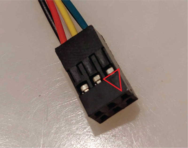
The Main Connector for the EasyPiezi has 6 pins, with Pin1 marked with a small embossed arrow:
Pin numbers are laid out in the following image and table:
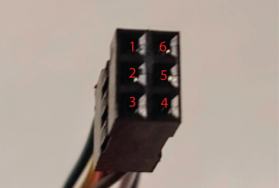
| Pin Number | Wire Color | Signal Name | Req/Opt |
|------------|------------|-------------|---------|
| 1 | Green | SDA (I2C) | Optional|
| 2 | Yellow | SCL (I2C) | Optional|
| 3 | Red | +6-12V DC | Required|
| 4 | Black | Ground | Required|
| 5 | White | Z-Trigger | Required|
| 6 | Blue | PT100 Anlg | Optional|
## Main Connector Sensor Side
The EasyPiezi's Main Connector Pinout is printed on the bottom of the board:
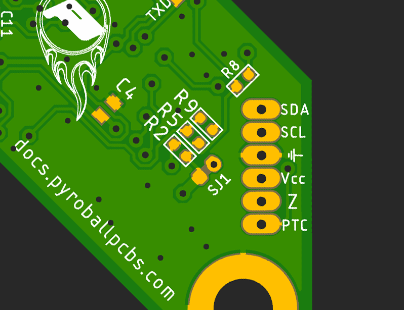
They are arranged from top to bottom:
| Pin Number | Wire Color | Signal Name | Req/Opt |
|------------|------------|-------------|---------|
| 1 | Green | SDA (I2C) | Optional|
| 2 | Yellow | SCL (I2C) | Optional|
| 3 | Black | Ground | Required|
| 4 | Red | +6-12V DC | Required|
| 5 | White | Z-Trigger | Required|
| 6 | Blue | PT100 Anlg | Optional|